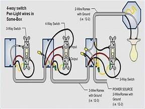
A 3 and 4 way switch is most convenient whenever the need to turn ON or OFF your lights from multiple locations. Your stairs for example, you can switch lights on or off at either end before ascending or descending. You may have an extended hallway with multiple exits or entrances; or a third floor with extended stairway:- You need to integrate a 4 way switch in circuit. I suspect that like me: you are bored reading, so i will post complimentary videos below on how to install a 3 and 4 way switch and for the most curios persons; l will include diagrams.
A 3 and 4 way switch is most convenient whenever the need to turn ON or OFF your lights from multiple locations. Your stairs for example, you can switch lights on or off at either end before ascending or descending. You may have an extended hallway with multiple exits or entrances; or a third floor with extended stairway:- You need to integrate a 4 way switch in circuit. I suspect that like me: you are bored reading, so i will post complimentary videos below on how to install a 3 and 4 way switch and for the most curios persons; l will include diagrams.
Typically most homes has a 3 and 4 way switch conveniently installed in area where illumination is needed at a distance.
This is a simple diagram of how 3 way switches operates in it’s on and off positions. please note: wires linking switches are known as ‘TRAVELERS’ When contacts are moved from one position to the other; the travelers transfer electricity to other switch for control. while switching on or off lights. It is very important to note that feeding the switch will be cable that has two wires plus ground. Always ground your switches. Between the two switches will be a cable with three wires and ground. (See video) You can easily add lights by connecting to existing in mounted box.
This is a simple diagram of how 3 way switches operates in it’s on and off positions. please note: wires linking switches are known as ‘TRAVELERS’ When contacts are moved from one position to the other; the travelers transfer electricity to other switch for control. while switching on or off lights. It is very important to note that feeding the switch will be cable that has two wires plus ground. Always ground your switches. Between the two switches will be a cable with three wires and ground. (See video) You can easily add lights by connecting to existing in mounted box.
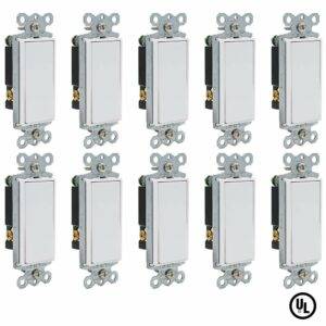
Below are images of a 3 and 4 way switch. Click on images for more information and for possible purchases.
One easy way to wire a 2 and 3 way switch is to make sure the load and source does not connect on the same switch. One switch should have the load while the other has the source. These must be connected on the black screw on each switch.
This videobelow shows how to install a 3 and 4 way switch and also wiring a 4 way switch into a 3 way circuit. The video however will help as you follow the visual. In this circuit you can also add lights by connecting in the same manner as you would do in the 3 way system. Now you can watch these two videos courtesy of DIY.
How A 3 and 4-way switch circuits work
Controlling a light with A 3 And 4 Way Switch.
This page describes how to use a 3 and 4 way switch to control lights from two or more locations. This is the first of several related diagram explaining how to control lights with multiple switches. Light can be controlled by more than one switch. The usual practice in home construction is to use 3 and 4 way switch to possibly control one or several lights. “3-way” is the electrician’s designation for a single pole double throw (SPDT) switch. A 3-way switch diagram is shown below.
This page describes how to use a 3 and 4 way switch to control lights from two or more locations. This is the first of several related diagram explaining how to control lights with multiple switches. Light can be controlled by more than one switch. The usual practice in home construction is to use 3 and 4 way switch to possibly control one or several lights. “3-way” is the electrician’s designation for a single pole double throw (SPDT) switch. A 3-way switch diagram is shown below.
Here is a typical circuit in its four possible states.:

The switches must create a complete circuit for current to flow and the bulb to light.
When both switches are up, the circuit is complete (top right). When both switches are down, the circuit is complete (bottom right). If one switch is up and one is down, the current reaches a dead end, no current flows and the bulb is off (top left and bottom left). Note that the above color scheme does NOT reflect wire color. It is functional coloring intended to illustrate the voltage state of each wire segment. Red indicates a hot wire (120 volts ac). Green indicates a neutral wire at ground potential. Blue indicates a wire that is floating. “Floating” here means isolated from hot and neutral by switches and/or light bulbs. For choosing wire color for your circuit, see later in this page.. Controlling a light with A 3 and 4 way switch or more. 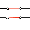 For more than two switches, one or more 4-way switches are added between the 3-way switches. A 4-way switch has two positions. In the first position, the contacts are connected straight through, so that the switch has no effect. In position two, the switch cross connects the contacts on the left with the contacts on the right, in an “X” connection. Below is one example of a 3 and 4 way switch light circuit. with two 4 way switches integrated. This circuit also shows rough-in boxes, wire nuts, and proper color code.
When both switches are up, the circuit is complete (top right). When both switches are down, the circuit is complete (bottom right). If one switch is up and one is down, the current reaches a dead end, no current flows and the bulb is off (top left and bottom left). Note that the above color scheme does NOT reflect wire color. It is functional coloring intended to illustrate the voltage state of each wire segment. Red indicates a hot wire (120 volts ac). Green indicates a neutral wire at ground potential. Blue indicates a wire that is floating. “Floating” here means isolated from hot and neutral by switches and/or light bulbs. For choosing wire color for your circuit, see later in this page.. Controlling a light with A 3 and 4 way switch or more.  For more than two switches, one or more 4-way switches are added between the 3-way switches. A 4-way switch has two positions. In the first position, the contacts are connected straight through, so that the switch has no effect. In position two, the switch cross connects the contacts on the left with the contacts on the right, in an “X” connection. Below is one example of a 3 and 4 way switch light circuit. with two 4 way switches integrated. This circuit also shows rough-in boxes, wire nuts, and proper color code.
 For more than two switches, one or more 4-way switches are added between the 3-way switches. A 4-way switch has two positions. In the first position, the contacts are connected straight through, so that the switch has no effect. In position two, the switch cross connects the contacts on the left with the contacts on the right, in an “X” connection. Below is one example of a 3 and 4 way switch light circuit. with two 4 way switches integrated. This circuit also shows rough-in boxes, wire nuts, and proper color code.
Note that the light can be placed anywhere in the return wire, shown above as white.
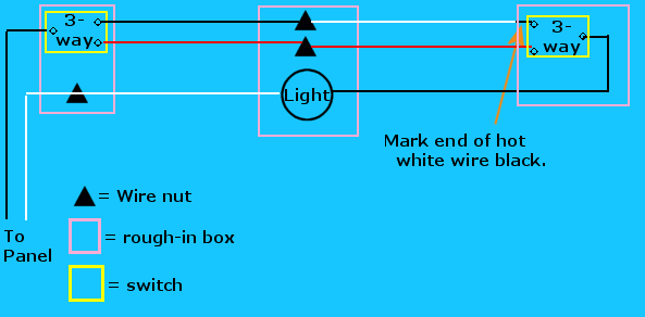
It may be as shown at the end of the run, but it may be between any pair of switch boxes (as shown in a later figure), or even between the panel and the first switch box. You can use as many 4-way switches as you like. Color coding. For the official word, consult the National Electric code. Here I will try to describe a bit of what the color coding is about, and how wires should be colored in lighting circuits (and why). Common practice in wiring a 3 and 4 way switch circuit is to use two-conductor (black and white) cable from panel to the first switch, and then three-conductor (black, red, white) cable between pairs of switches. White denotes neutral, a current carrying wire that is bonded to ground in the circuit breaker panel. Black and red are used for “hot” conductors 120 volts with respect to ground. The previous figure shows a circuit that follows this convention. The NEC allows certain exceptions to this in lighting circuits, so that standard two-conductor (black and white) and three-conductor (black, red, and white) can be used, and used efficiently. In particular, it is often convenient and efficient to place a light between two switches or between the panel and the first switch. In such cases, it is convenient and permissible to bring 120 volts to a switch via a white wire. If you place a light in such a location, please be aware of the confusion that can occur from this wire color. In the above picture, white is always neutral, while black or red may be hot. If the light is located between the middle two switches, then the white wire leading from the light to a switch is, in fact, sometimes hot. To avoid confusion and to conform to code, use a black marker to mark any “hot” white wire feeding a switch. Such color coding is shown in the following example:
It may be as shown at the end of the run, but it may be between any pair of switch boxes (as shown in a later figure), or even between the panel and the first switch box. You can use as many 4-way switches as you like. Color coding. For the official word, consult the National Electric code. Here I will try to describe a bit of what the color coding is about, and how wires should be colored in lighting circuits (and why). Common practice in wiring a 3 and 4 way switch circuit is to use two-conductor (black and white) cable from panel to the first switch, and then three-conductor (black, red, white) cable between pairs of switches. White denotes neutral, a current carrying wire that is bonded to ground in the circuit breaker panel. Black and red are used for “hot” conductors 120 volts with respect to ground. The previous figure shows a circuit that follows this convention. The NEC allows certain exceptions to this in lighting circuits, so that standard two-conductor (black and white) and three-conductor (black, red, and white) can be used, and used efficiently. In particular, it is often convenient and efficient to place a light between two switches or between the panel and the first switch. In such cases, it is convenient and permissible to bring 120 volts to a switch via a white wire. If you place a light in such a location, please be aware of the confusion that can occur from this wire color. In the above picture, white is always neutral, while black or red may be hot. If the light is located between the middle two switches, then the white wire leading from the light to a switch is, in fact, sometimes hot. To avoid confusion and to conform to code, use a black marker to mark any “hot” white wire feeding a switch. Such color coding is shown in the following example:
Other variations
Here are another couple of variations of a 3- and 4-way switch in circuits.
All the 4-way switches are optional. If you only need two switches, leave out both the 4-way switches. You can also add as many 4-way switches as you like in place of any one shown in the circuits that follow. Here is an example of a light in the middle of the run. Notice the pattern is very similar, but the color code is a little trickier. Two of the white wires must be remarked black where the feed the switches.
All the 4-way switches are optional. If you only need two switches, leave out both the 4-way switches. You can also add as many 4-way switches as you like in place of any one shown in the circuits that follow. Here is an example of a light in the middle of the run. Notice the pattern is very similar, but the color code is a little trickier. Two of the white wires must be remarked black where the feed the switches.

By marking the wire as above, you are informing anyone working in the box later that this is the wire that will deliver (occasionally) 120 volts to the switch.
This will enable the worker to properly wire replacement switches. (For circuits with only two switches, just ignore the 4-way switches in the above figure.) Here in this 3 and 4 way switch circuit, one more variation, with the cable from the panel going directly to the light box, which is in turn between some of the switches..
This will enable the worker to properly wire replacement switches. (For circuits with only two switches, just ignore the 4-way switches in the above figure.) Here in this 3 and 4 way switch circuit, one more variation, with the cable from the panel going directly to the light box, which is in turn between some of the switches..

Troubleshooting A 3 and 4 Way Switch Circuits
The most likely cause of circuit failure in a 3 and 4 way switch circuit is an error in the wiring arrangement. Verify the circuit is wired correctly using the following guidelines: In a 3 and 4 way switch circuit; 4 way switch must be wired between two 3 way switches as shown in the diagrams on this page. A 4 way switch has five terminals: one ground and 4 circuit terminals divided into two matching pairs called travelers. Each pair of traveler terminals should be wired to the traveler wires from one of the 3 way switches in the circuit. The travelers from one 3 way can be wired to either terminal in a pair, but don’t mix up the pairs on the 4 way or the circuit won’t work properly. Check to be sure the traveler wires only connect between the traveler terminals on all the switches.In a 3 and 4 way switch circuit, 4 way switch will only be connected to traveler wires, never to a hot source or load wire and never to a neutral wire. Also, confirm that each pair of travelers on a 4 way are only connected to one switch per pair. Check that the neutral from the source is only connected to the neutral terminal at the load. A neutral wire will never be connected to standard 3 and 4 way switch, although some smart switches and timers may make use of a neutral wire to operate the device. If you believe your circuit is wired correctly and the lights still don’t work, one or more of the switches may be defective.
The most likely cause of circuit failure in a 3 and 4 way switch circuit is an error in the wiring arrangement. Verify the circuit is wired correctly using the following guidelines: In a 3 and 4 way switch circuit; 4 way switch must be wired between two 3 way switches as shown in the diagrams on this page. A 4 way switch has five terminals: one ground and 4 circuit terminals divided into two matching pairs called travelers. Each pair of traveler terminals should be wired to the traveler wires from one of the 3 way switches in the circuit. The travelers from one 3 way can be wired to either terminal in a pair, but don’t mix up the pairs on the 4 way or the circuit won’t work properly. Check to be sure the traveler wires only connect between the traveler terminals on all the switches.In a 3 and 4 way switch circuit, 4 way switch will only be connected to traveler wires, never to a hot source or load wire and never to a neutral wire. Also, confirm that each pair of travelers on a 4 way are only connected to one switch per pair. Check that the neutral from the source is only connected to the neutral terminal at the load. A neutral wire will never be connected to standard 3 and 4 way switch, although some smart switches and timers may make use of a neutral wire to operate the device. If you believe your circuit is wired correctly and the lights still don’t work, one or more of the switches may be defective.
Wiring A 3 And 4 Way Switch Circuit and 2 Lights
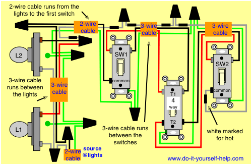
This drawing shows the wiring for multiple lights in a 3 and 4 way switch circuit with the source and fixtures coming before the switches. More lights can be added to this circuit by duplicating the wiring shown here for each additional fixture. Here 3-wire cable runs between L1 and L2, 2-wire cable runs from the last light to SW1, and more 3-wire cable runs from SW1 to the 4 way switch and then to SW2. At the lights the hot source is spliced to the black wire running between lights, it does not connect to the lights. At the last fixture it is spliced to the black wire running to the common on SW1. The neutral from the source is connected to each light fixture with a pigtail and to the neutral running to the next light. At the last light the source neutral is connected directly to the fixture neutral terminal. The red wire between the lights is connected directly to the hot on L1 and then run to the next light. If there are more than 2 lights, the red is pigtailed to the fixture hot and to the red wire running on to the next light. With 2 lights, it is spliced with the white wire running to the switches. This white wire is wrapped with black tape to mark it as hot. At SW1 this marked white wire is spliced to the marked white running to the 4 way switch and at the 4 way, it is spliced again to the marked white wire running directly to the common terminal on SW2. This white wire does not connect to the 4 way switch. The black and red wires running between the switches serve as the travelers for the circuit. At the 4 way the travelers from SW1 connect to the two terminals at T1. The two terminals at T2 connect to the black and red travelers running to SW2.
This drawing shows the wiring for multiple lights in a 3 and 4 way switch circuit with the source and fixtures coming before the switches. More lights can be added to this circuit by duplicating the wiring shown here for each additional fixture. Here 3-wire cable runs between L1 and L2, 2-wire cable runs from the last light to SW1, and more 3-wire cable runs from SW1 to the 4 way switch and then to SW2. At the lights the hot source is spliced to the black wire running between lights, it does not connect to the lights. At the last fixture it is spliced to the black wire running to the common on SW1. The neutral from the source is connected to each light fixture with a pigtail and to the neutral running to the next light. At the last light the source neutral is connected directly to the fixture neutral terminal. The red wire between the lights is connected directly to the hot on L1 and then run to the next light. If there are more than 2 lights, the red is pigtailed to the fixture hot and to the red wire running on to the next light. With 2 lights, it is spliced with the white wire running to the switches. This white wire is wrapped with black tape to mark it as hot. At SW1 this marked white wire is spliced to the marked white running to the 4 way switch and at the 4 way, it is spliced again to the marked white wire running directly to the common terminal on SW2. This white wire does not connect to the 4 way switch. The black and red wires running between the switches serve as the travelers for the circuit. At the 4 way the travelers from SW1 connect to the two terminals at T1. The two terminals at T2 connect to the black and red travelers running to SW2.
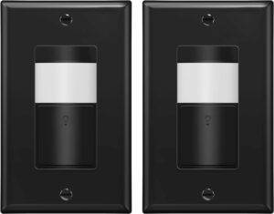
Sensor 3 and 4 way switch detects motion to automatically turn lights on and off based on the occupancy and vacancy in a room. Motion sensor 3 an 4 way switch uses a passive infrared (PIR) sensor to reduce false triggers from unwanted movements. Motion sensor wall switch has universal wiring design with interchangeable hot and load wires makes installation easier. Occupancy sensor mode (Auto ON, Auto OFF) and vacancy sensor mode (Manual ON, Auto OFF) allow you to customize the sensor according to your needs; fixed time delays: 15 sec (Test), 5 min, 10 min, 20 min, 30 min; adjustable range. Neutral wire not required, ground wire required for installation; 1200 square feet coverage area, 180-degree field of view; 120-277VAC, 500W incandescent/halogen, 250W CFL/LED, 1/8HP motor; operating temperature (32 – 131°F); single pole only; 2x wall plates included.
Sensor 3 and 4 way switch detects motion to automatically turn lights on and off based on the occupancy and vacancy in a room. Motion sensor 3 an 4 way switch uses a passive infrared (PIR) sensor to reduce false triggers from unwanted movements. Motion sensor wall switch has universal wiring design with interchangeable hot and load wires makes installation easier. Occupancy sensor mode (Auto ON, Auto OFF) and vacancy sensor mode (Manual ON, Auto OFF) allow you to customize the sensor according to your needs; fixed time delays: 15 sec (Test), 5 min, 10 min, 20 min, 30 min; adjustable range. Neutral wire not required, ground wire required for installation; 1200 square feet coverage area, 180-degree field of view; 120-277VAC, 500W incandescent/halogen, 250W CFL/LED, 1/8HP motor; operating temperature (32 – 131°F); single pole only; 2x wall plates included.


TOP GREENER TDOS5-J PIR Motion Sensor 3 and 4 way Switch, No Neutral Required
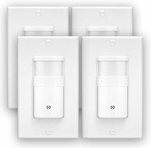
Savings & Convenience in One Switch. The TOPGREENER TDOS5-J-W combines occupancy and vacancy sensors into one motion sensor switch for energy efficiency, security and convenience. The 2-in-1 motion sensor 3 and 4 way switch detects occupancy and vacancy in a room to automatically turn lights or fans on and off. Enjoy hands-free convenience by never having to fumble in the dark looking for the switch. Give yourself one less thing to worry about by having the peace of mind that your lights will always automatically shut off.
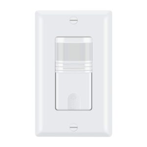
The TDOS5-J 3 and 4 way switch version does not require a neutral wire for installation, but it requires a ground wire for it to work properly. Specifications: 120-277VAC; 500W Incandescent/Halogen, 250W CFL/LED, 1/8HP Motor Automatic On/Automatic Off; Manual On/Automatic Off. Single-pole use only. Neutral wire not required. Wall plates included
The TDOS5-J 3 and 4 way switch version does not require a neutral wire for installation, but it requires a ground wire for it to work properly. Specifications: 120-277VAC; 500W Incandescent/Halogen, 250W CFL/LED, 1/8HP Motor Automatic On/Automatic Off; Manual On/Automatic Off. Single-pole use only. Neutral wire not required. Wall plates included
Enjoy energy savings, enhanced safety and security
|
|
|
|---|---|---|
Energy Savings
Save money on your energy bill by making sure unused lights and fans are always turned off with a motion sensor switch. Vacancy mode’s manual-on feature saves further energy by ensuring lights and fans are turned on only when needed with a motion sensor switch. Avoid having lights accidentally left on all day.
| Security & Safety | Convenience |

Custom Settings
With advanced technology packed into intuitive and easy-to-use settings, you can easily adjust the 3 and 4 way switch length of time lights will stay on or how sensitive the sensor is to motion. Make your home smarter in one switch!
Occupancy (OCC) Mode: Detects occupancy and vacancy in a room for full automation of lights, fans, or other loads. The sensor will automatically turn On/Off when triggered by motion. When no motion is detected within the delay time, the lights will turn off automatically.
Vacancy (VAC) Mode: Detects vacancy in a room to automatically turn lights off. Lights are manually turned on when entering the room. When no motion is detected within the delay time, the lights will turn off automatically
.
With advanced technology packed into intuitive and easy-to-use settings, you can easily adjust the 3 and 4 way switch length of time lights will stay on or how sensitive the sensor is to motion. Make your home smarter in one switch!
Occupancy (OCC) Mode: Detects occupancy and vacancy in a room for full automation of lights, fans, or other loads. The sensor will automatically turn On/Off when triggered by motion. When no motion is detected within the delay time, the lights will turn off automatically.
Vacancy (VAC) Mode: Detects vacancy in a room to automatically turn lights off. Lights are manually turned on when entering the room. When no motion is detected within the delay time, the lights will turn off automatically
NEUTRAL WIRE REQUIRED:
This motion sensor 3 and 4 way switch need neutral wire. Please review your wiring setup prior to purchase. Single Pole or 3 and four Way switch available. If you need 3-way function, you need to connect all 5 wires. If you do not need 3-way function, please do not connect the blue wire, just connect other 4 wires. Lights will flash if not correctly connected. If you have any doubt, please consult with a licensed electrician. 3-WAY SWITCH: This motion sensor occupancy switch is a 3-way switch allowing the lights to turn on from multiple switch locations in the room. The motion sensor covers 180°, so all motion is detected. Light switch sensor features adjustable settings. Automatic ON /OFF and Manual ON/Automatic OFF operation, Adjustable time delay from 15sec-1min-5mins-15mins-30mins, Adjustable sensitivity, Adjustable Light level sensing. Occupancy switch mode (Auto ON, Auto OFF) and vacancy switch mode (Manual ON, Auto OFF) allow you to customize the sensor according to your needs. Save money on your energy bill by making sure unused lights and fans are always turned off with a motion sensor switch. Vacancy mode’s manual-on feature saves further energy by ensuring lights and fans are turned on only when needed with a motion sensor switch. Avoid having lights and fans accidentally left on all day.
This motion sensor 3 and 4 way switch need neutral wire. Please review your wiring setup prior to purchase. Single Pole or 3 and four Way switch available. If you need 3-way function, you need to connect all 5 wires. If you do not need 3-way function, please do not connect the blue wire, just connect other 4 wires. Lights will flash if not correctly connected. If you have any doubt, please consult with a licensed electrician. 3-WAY SWITCH: This motion sensor occupancy switch is a 3-way switch allowing the lights to turn on from multiple switch locations in the room. The motion sensor covers 180°, so all motion is detected. Light switch sensor features adjustable settings. Automatic ON /OFF and Manual ON/Automatic OFF operation, Adjustable time delay from 15sec-1min-5mins-15mins-30mins, Adjustable sensitivity, Adjustable Light level sensing. Occupancy switch mode (Auto ON, Auto OFF) and vacancy switch mode (Manual ON, Auto OFF) allow you to customize the sensor according to your needs. Save money on your energy bill by making sure unused lights and fans are always turned off with a motion sensor switch. Vacancy mode’s manual-on feature saves further energy by ensuring lights and fans are turned on only when needed with a motion sensor switch. Avoid having lights and fans accidentally left on all day.
